Precision die cutting covers a family of processes that convert a web of material into a finished shape: a CGM patch, a test strip spacer, a wound dressing island, a sensor electrode. The process is simple to describe and difficult to execute, because the tolerances that matter are measured in tenths of a millimetre on materials that move, stretch and adhere to things they should not.
This article compares the main process routes, explains the tooling and registration decisions behind them, and maps each route to the medical applications where it performs best.
What Precision Die Cutting Actually Includes
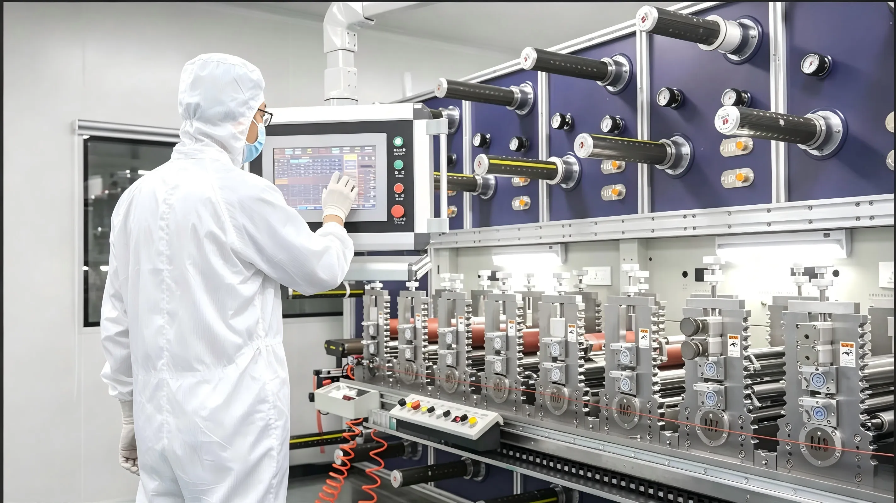
A die cutting line is rarely just a press. It includes unwind and tension control, lamination stations, printing or coating where required, the cutting station itself, waste matrix removal, and rewind or sheet-fed output. For medical components, it also includes inspection and a controlled environment.
That means evaluating a supplier on the whole line, not only on the press. A converter with an excellent rotary press and weak tension control will deliver inconsistent parts, because tension variation changes registration and cut quality before the die is reached.
Rotary, Flatbed, Laser and Waterjet
Rotary die cutting runs a continuous web through a rotating cylindrical die. It is fast, holds registration well at high volume, and is the standard route for adhesive components such as CGM patches and spacer tapes. Tooling cost is higher and lead time longer, so it rewards programs with stable design and predictable demand.
Flatbed die cutting uses a reciprocating press, either sheet-fed or web-fed. It handles complex outlines, short runs and thick or multi-layer stacks more economically, and tooling is cheaper and faster to produce. Cycle time per stroke is longer, which matters at high volume.
Laser cutting removes tooling entirely for the cut path, which makes design iteration fast and supports intricate geometry, small holes and rapid prototypes. It is slower per part, generates heat and plume that must be managed around adhesives, and produces a slightly different edge than a mechanical die.
Waterjet cutting avoids thermal effects and suits thick or hard materials, but introduces moisture and requires drying before adhesive assembly. It is rarely the first choice for thin adhesive laminates.
| Route | Typical strength | Typical limitation | Best for |
|---|---|---|---|
| Rotary | Speed, registration, consistency | Tooling cost and lead time | High-volume adhesive patches, spacer tape |
| Flatbed | Complex outlines, low tooling cost | Lower throughput | Prototypes, short runs, thick stacks |
| Laser | No tooling, intricate geometry | Speed, heat effects on adhesive | Prototyping, small features, revisions |
| Waterjet | No thermal effect, thick materials | Moisture, secondary drying | Thick or hard substrates |
Tooling: Hardened Steel and Flexible Dies
Rotary tooling is usually hardened steel, machined to the geometry and mounted on a cylinder. It is durable across millions of impressions and holds tolerance well, but it is expensive and takes weeks to manufacture and qualify. Ownership and revision terms should be agreed in writing before the first cut.
Flexible dies are thin, chemically etched plates mounted magnetically. They are cheaper and faster to produce, useful for flatbed work and for design iterations, but they wear faster and need more frequent replacement at high volume. For a program moving from prototype to serial production, a flexible die for the trial phase and hardened tooling for production is a normal progression.
Tool life is a wear question, not a calendar question. A die that cuts abrasive filled materials wears differently from one cutting a soft adhesive film, and monitoring should be based on cut quality measurements rather than on impression counts alone.
Kiss Cut, Through Cut and Multi-Layer Cutting
Adhesive components are usually kiss cut: the die cuts the upper layers and stops at the release liner, leaving a continuous liner that carries the parts through the line. Kiss cutting demands precise depth control, because a die that cuts too deep destroys the liner and a die that cuts too shallow leaves the part attached by a thin skin of adhesive.
Through cutting separates parts entirely and is used where the liner is not required as a carrier. Multi-layer cutting, where several materials are cut in one stroke, saves registration operations but demands that all layers share compatible cutting behaviour. A soft foam over a hard film will cut differently in the same die.
The choice affects downstream handling more than it affects the cut itself. Kiss-cut parts can be wound, stacked and shipped on the liner; through-cut parts usually need pick-and-place or packaging immediately.
Registration, Vision and Tolerances
Registration is the alignment between features: cut to print, cut to electrode, cut to adhesive zone. On a rotary line it is held by tension and by printed fiducial marks read by a vision system. On a flatbed line it depends more on sheet alignment.
Specify tolerances per feature rather than one global value. An outer profile can often tolerate a wider band than a sensor opening or an electrode registration, and treating them identically either drives cost unnecessarily or accepts risk where it matters.
Capability data should be presented as a distribution, not a single inspection result. A converter that reports Cp or Cpk values across multiple lots is giving you information; one that reports a certificate is giving you an assertion.
Materials and Their Converting Behaviour
Medical converting handles films, foams, nonwovens, papers, foils and laminates. Thin PET and polyurethane films cut cleanly but are sensitive to tension. Soft foams compress and recover, which changes the effective cut dimension. Nonwovens fray at the edge unless the die is sharp and the web is under correct tension. Adhesive-coated materials require cold temperatures or release agents in some cases to prevent sticking to the die.
Each material combination has a practical edge quality limit. Asking for a razor edge on a soft foam is a request the process cannot satisfy, and a converter should say so rather than accept the drawing.
Application Map
CGM patches and overpatches: rotary kiss cutting of laminates with concentric openings and tight registration. BGM spacer tapes and diagnostic components: high-precision slitting and lamination with thickness-critical channels. Wearable device adhesives: flatbed or rotary cutting of complex outlines on breathable carriers. Wound care: multi-layer island dressings, often flatbed for thick stacks. Electrodes and sensor pads: conductive materials with registration to printed traces.
The common thread is that the process follows the geometry, the volume and the material, not the other way round.
What Drives Cost
Four factors dominate. Tooling amortisation depends on volume and on how often the design changes. Material yield depends on web width utilisation, so nesting parts efficiently on the web is a design decision with cost consequences. Line speed depends on material and on the number of stations. And inspection cost rises with tolerance demands, because tighter specifications require more measurement.
The cheapest quote often assumes the widest tolerance and the lowest yield. Comparing quotes without normalising those assumptions is comparing different products.
Frequently Asked Questions
What tolerance can precision die cutting hold on adhesive components?
On rotary lines with vision registration, tenths of a millimetre on outer profiles are routine, and tighter on selected features such as sensor openings. The achievable value depends on material, geometry and registration requirements.
When should a program use laser instead of a die?
During design iteration, for intricate geometry that would make tooling expensive, and for low volumes where tooling cost dominates. For high-volume adhesive parts, rotary die cutting is usually faster and cheaper per unit.
What is kiss cutting and why does it matter?
Kiss cutting cuts the part layers but leaves the release liner intact so parts stay on a continuous carrier. Depth control is critical: too deep destroys the liner, too shallow leaves the part attached.
Who should own the die cutting tooling?
The device manufacturer should own or have a release right to the tooling, with documented revision control. Otherwise changing suppliers means paying for a new tool and repeating qualification.
How is registration verified on a rotary line?
Printed fiducial marks read by a vision system during running, with capability data across lots. Ask for the Cp or Cpk values rather than a single inspection certificate.
Can one die cut a multi-layer stack in a single stroke?
Often yes, but only when the layers have compatible cutting behaviour. Soft foam over hard film typically cuts unevenly, so the stack may need separate stations.
Conclusion
Precision die cutting is a process selection problem before it is a purchasing problem. Match the route to the geometry, volume and material, specify tolerances per feature, and demand capability data rather than certificates. The converter that can explain why a particular route suits your part is the one worth quoting.
Leetoya runs rotary and flatbed die cutting, precision slitting, lamination and laser cutting for medical adhesive components, with ISO 13485 quality systems and ISO Class 7 cleanroom production. Start with die cutting capabilities or the full manufacturing capability overview.
Request a drawing review. Send the outline, layer stack, tolerance callouts and annual volume, and we will recommend a process route before tooling is committed. Contact our engineering team.